Brief background of IEEE802 standards for LAN and
MAN
While connecting computers through networks we need to have
set of rules/standards for the data to travel from one computer to other
computer. The right example for this can be road traffic rules. It's self
understood, why we need traffic rules while driving, in same sense for the data
packets to travel from one computer terminal to other terminal they should also
follow set of rules and regulations.
One such set of rules for the networking traffic to follow is IEEE802
standards. Its developed by IEEE (Institute of Electrical and Electronics
Engineers, Inc.) The IEEE is the world's leading professional association for
the advancement of technology. It's a non- profit organization offering its
members immense benefits.
The standards such as IEEE 802 helps industry provide advantages such as,
interoperability, low product cost, and easy to manage standards.
IEEE standards deal with only Local Area Networks (LAN) and
Metropolitan Area Networks (MAN). See in the figure below, to know where
exactly the IEEE802 standards are used in a OSI layer.
The IEEE 802 standards are further divided into many parts. They
are,
IEEE 802.1 Bridging (networking) and Network Management
IEEE 802.2 Logical link control (upper part of data link layer)
IEEE 802.3 Ethernet (CSMA/CD)
IEEE 802.4 Token bus (disbanded)
IEEE 802.5 Defines the MAC layer for a Token Ring (inactive)
IEEE 802.6 Metropolitan Area Networks (disbanded)
IEEE 802.7 Broadband LAN using Coaxial Cable (disbanded)
IEEE 802.8 Fiber Optic TAG (disbanded)
IEEE 802.9 Integrated Services LAN (disbanded)
IEEE 802.10 Interoperable LAN Security (disbanded)
IEEE 802.11 Wireless LAN & Mesh (Wi-Fi certification)
IEEE 802.12 demand priority (disbanded)
IEEE 802.13 Not Used
IEEE 802.14 Cable modems (disbanded)
IEEE 802.15 Wireless PAN
IEEE 802.15.1 (Bluetooth certification)
IEEE 802.15.4 (ZigBee certification)
IEEE 802.16 Broadband Wireless Access (WiMAX certification)
IEEE 802.16e (Mobile) Broadband Wireless Access
IEEE 802.17 Resilient packet ring
IEEE 802.18 Radio Regulatory TAG
IEEE 802.19 Coexistence TAG
IEEE 802.20 Mobile Broadband Wireless Access
IEEE 802.21 Media Independent Handoff
IEEE 802.22 Wireless Regional Area Network
Here we discuss most popular and key parts of above list
IEEE 802.3 Ethernet (CSMA/CD)
A method called Carrier Sense Multiple Access with Collision
Detection (CSMA/CD) was used to send data over shared single co-axial cable
connected to all computers on a network. In this method, the computer terminals
(also called as stations) transmits the data over cable whenever the cable is
idle, If more than one station transmit at same time and if they collide, the
transmission will be stopped by such stations. They will wait for some random
time and restart transmission.
The concept of sharing single cable
or wire between multiple stations was used for first time in Hawaiian Islands.
It was called ALOHA systems; built to allow radio communication between
machines located at different places in Hawaiian Islands. Later Xerox PARC
built a 2.94 mbps CSMA/CD system to connect multiple personal computers on a
single cable. It was named as Ethernet.
Ethernet or IEEE802.3 standards only define MAC (Data link) and Physical layer
of standard OSI model.
Wiring and cabling standards of 802.3
There are four cabling standards as per 802.3, each one has
evolved over the time for their special advantages.
The four types of cables are,
1. 10Base5
2. 10Base2
3. 10Base-T
4. 10Base-F
The table below compares all four types of cables
Technical Name
|
Cable/Wire type
|
Max. Segment/wire Length
|
Maximum number of Nodes/Segment
|
Advantages
|
10Base5
|
Thick coaxial
|
500 meters
|
100
|
Long cable length
|
10Base2
|
RG58 (thin) coaxial
|
185 meters
|
30
|
Low cost
|
10BaseT
|
Twisted pair (like telephone wire)
|
100 meters
|
1024
|
Easy to maintain
|
10BaseF
|
Fiber-optic
|
2,000 meters
|
1024
|
No noise interference
|
The 10 in the technical name refer to data speed of
10Mbits/sec.
"Link Integrity" and "Auto-partition" are part of the
10BaseT specification. This means that all network equipment claiming
compliance with 10BaseT must support Link Integrity and Auto-partitioning.
10Base5
10 Base5 is also called as ThickNet or thick Ethernet. It uses RG-8 thick
coaxial trunk cable, which looks like orange colored garden hose. The cable is
tapered with taps called vampire taps in which a pin is carefully forced
halfway into the cable's core. The connection can be made to the desired
computer network interface card (NIC) from these vampire taps. ThickNet can
travel 500 meters per segment, and it can have a maximum of 100 taps per segment.
Each tap requires a minimum distance of 2.5 meters before the next tap and has
a maximum drop distance of 50 meters. The cable must be terminated with a
50-ohm terminator resistor.
Due to its complex and slow nature 10Base5 is no more
preferred. The severe drawback is entire line will fail for any single failure
on the trunk. This cable can be termed as obsolete/outdated technology.
 The one plus point of ThickNet is that, once it's up and
running, it will continue to do so until you tell it otherwise. Although it is
slow and unwieldy, 10Base5 technology is very reliable.
The one plus point of ThickNet is that, once it's up and
running, it will continue to do so until you tell it otherwise. Although it is
slow and unwieldy, 10Base5 technology is very reliable.
Here is the figure showing how the cables are
connected to Network Interface Cards inside the computer using 10base5.
10Base2
10Base2 is not very different from 10 Base5. The most notable physical
difference between 10Base2 and 10Base5 is the size of the co-axial cable.
10Base2 is thinner than the 10Base5 and so is called as ThinNet or thin
Ethernet. Another difference is that 10Base2 is set up in a daisy chain. Daisy
chain is a wiring scheme in which, for example, device A is wired to device B,
device B is wired to device C, device C is wired to device D, et cetera.
10Base2 uses BNC connectors attached to a thin coaxial
cable. The maximum segment length of 10Base2 is 185 meters, and the maximum
number of devices per segment is 30.
10Base is also outdated/obsolete technology. In rare cases
it could be deployed as a backbone for a network.
10Base-T
10Base-T is the most popular cabling method. Its also called Standard Ethernet,
or twisted pair, 10Base-T works on a star topology connecting all computers to
a hub. It is best used with Category 5 cable (so it can be upgraded to Fast
Ethernet) and can have a maximum of three hubs daisy-chained together.
Since it is simple and cheap to implement it is most opted
one. The specifications of Standard Ethernet include the following:
It uses RJ45 connectors on unshielded twisted-pair (UTP) cable.
The maximum cable length is 100 meters (before a repeater is needed).
The maximum number of devices per segment is 1,024 (although performance will
become quite poor before that number is ever reached).
The 10Base-T standard is best employed within a LAN where
cost is a factor-and speed and distance are not.
Link Integrity is concerned with the condition of the cable
between the network adapter and the hub. If the cable is broken, the hub will
automatically disconnect that port.
Auto partitioning occurs when an Ethernet hub port experiences more than 31
collisions in a row. When this happens, the hub will turn off that port,
essentially isolating the problem.
10Base-F
In 10BaseF the twisted copper wires are replaced by a optical fiber. 10Base-F
uses a higher quality cabling technology, multimode (or single-mode)
fiber-optic cable, to transport data. The particular technology has two
subdivisions that must be addressed: the newer 10Base-FL and 10BaseFOIRL.
Because it is older, the 10BaseFOIRL (Fiber-optic
Inter-repeater Link) technology doesn't have quite the capabilities of the
newer 10Base-FL. With 10BaseFOIRL, you have the following specs:
It's based on IEEE 802.3.
The segment length is 1,000 meters.
There are three sizes of duplex multimode fiber: 50-, 62.5-, or 100-micron. Of
these three, 62.5-micron is the most common.
ST or SMA 905 connectors are used by 10BaseFOIRL.
It must be used in a star configuration.
AUI connectors have to be connected to fiber transceivers.
The much-improved 10Base-FL technology offers a different
set of specs:
It's based on the 10Base-F IEEE 802.3 spec.
It's able to interoperate with FOIRL and is designed to replace the FOIRL
specification.
The segment length is 2,000 meters (if exclusively using 10Base-FL).
The maximum number of devices per segment is two; one is the station and the
other is the hub.
The maximum number of repeaters that may be used between devices is two.
NICs with standard AUI ports must use a fiber-optic transceiver.
The benefits of optical fiber are,
No radio or magnetic interference.
Transmissions are safe from electronic bugging,
Cable is extremely lightweight,
10Base-FL fiber-optic technologies are best implemented in
long runs where reliability and security are critical.
IEEE802.4:
Token bus
In this system, the nodes are
physically connected as a bus, but logically form a ring with tokens passed
around to determine the turns for sending. It has the robustness of the 802.3
broadcast cable and the known worst case behavior of a ring. The structure of a
token bus network is as follows:
Token bus or 802.4 is more robust and reliable than 802.3
frames. The standard 802.4 is a linear or tree shaped cable onto which the
stations are attached.
Network
is a physical bus but a logical ring. The stations are numbered and are allowed
to access the medium sequentially. If there are n stations, and packet
transmission time is bounded to T, then the maximum waiting time is nT. Token
bus MAC is simple and robust. Token bus is mostly used in automation systems.
Data is subdivided into four priority classes. Each station has four packet
queues, one for each priority. When a station receives token, it is allowed to
transmit certain fixed time. During that time it transmits packets in the
decreasing order of priorities.
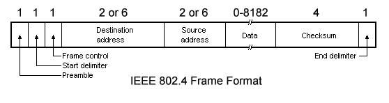
Frame Structure:
A 802.4 frame has the following
fields:
Preamble: The Preamble is for synchronizing the receiver's clock.
Starting Delimiter (SD) and End Delimiter (ED): The SD and ED fields are
used to mark frame boundaries. Both contain analog encoding of symbols other
than 1 or 0 so that they cannot occur accidentally in the user data. Lengthy
field is no more needed.
Frame Control (FC): FC is used to distinguish data frames from control
frames. Data frames carries the frame's priority as well as a bit which the
destination can set as an acknowledgement. For control frames, the Frame
Control field is used to specify the frame type. Token passing and various ring
maintenance frames are the allowed frame types.
Destination and Source Address: The Destination and Source address
fields may be of 2 bytes (for a local address) or 6 bytes (for a global
address).
Data: This is the actual data and it is of 8182 bytes when 2 byte
addresses are used and 8174 bytes for 6 byte addresses.
Checksum: A 4-byte checksum of the data for error detection.
IEEE 802.5: Token Ring Network
Token
Ring is formed by the nodes connected in ring format as shown in the diagram
below.
The
principle used in the token ring network is that a token is circulating in the
ring and whichever node grabs that token will have right to transmit the data.
Whenever a station wants to transmit a frame it inverts a single bit of the
3-byte token which instantaneously changes it into a normal data packet.
Because there is only one token, there can atmost be one transmission at a
time.
Since the token rotates in the ring it is guarenteed that every node gets the
token with in some specified time. So there is an upper bound on the time of
waiting to grab the token so that starvation is avoided.
There is also an upper limit of 250 on the number of nodes in the network. To
distinguish the normal data packets from token (control packet) a special
sequence is assigned to the token packet. When any node gets the token it first
sends the data it wants to send, then recirculates the token.
If
a node transmits the token and nobody wants to send the data the token comes
back to the sender. If the first bit of the token reaches the sender before the
transmission of the last bit, then error situation araises. So to avoid this we
should have:
propogation
delay + transmission of n-bits (1-bit delay in each node ) > transmission of
the token time
A
station may hold the token for the token-holding time. which is 10 ms unless
the installation sets a different value. If there is enough time left after the
first frame has been transmitted to send more frames, then these frames may be
sent as well. After all pending frames have been transmitted or the
transmission frame would exceed the token-holding time, the station regenerates
the 3-byte token frame and puts it back on the ring.
802.11 Wireless LAN Standards
Provides
network connectivity over wireless media
An
Access Point (AP) is installed to act as Bridge between Wireless and Wired
Network
The
AP is connected to wired network and is equipped with antennae to provide
wireless connectivity
Range
( Distance between Access Point and WLAN client) depends on structural
hindrances and RF gain of the antenna at the Access Point
To
service larger areas, multiple APs may be installed with a 20-30% overlap
A
client is always associated with one AP and when the client moves closer to
another AP, it associates with the new AP (Hand-Off)
Three
flavors:
Standard
|
Data Transfer Rate(Max)
|
Typical Indoor Range
|
Frequency
|
802.11b
|
11Mb/s
|
100-150feet
|
2.4Ghz
|
802.11g
|
54Mb/s
|
100-150feet
|
2.4Ghz
|
802.11a
|
54Mb/s
|
25-70feet
|
5Ghz
|
Fibre Distributed Data Interface (FDDI)
Fiber
Distributed Data Interface (FDDI) is an expensive LAN technology that employs a
pair of fibre-optic rings. One is primary ring and the second ring is used to
replace the primary ring in the case of a network failure. Fiber Distributed
Data Interface (FDDI) uses fiber-optic cable and is wired in a ring topology
and Fiber Distributed Data Interface (FDDI) uses token passing as its
media-access method and can operate at high speeds.
The
Fiber Distributed Data Interface (FDDI) provides high-speed network backbones
that can be used to connect and extend LANs.
Like
token ring, FDDI also has error-detection and correction capabilities. In a
normally operating Fiber Distributed Data Interface (FDDI) ring, the token
passes by each network device fast. If the token is not seen within the maximum
amount of time that it takes to circulate the largest ring, it indicates a
network problem.
Fiber-optic
cable such as the cable used with Fiber Distributed Data Interface (FDDI) can
support very large volumes of data over large distances.
Fiber
Distributed Data Interface (FDDI) is an expensive technology to set up because
the network devices require a special network card and also fiber-optic cabling
is required, which is expensive than twisted-pair cable. Because most Fiber Distributed
Data Interface (FDDI) installations use a redundant second ring, more cabling
is required.